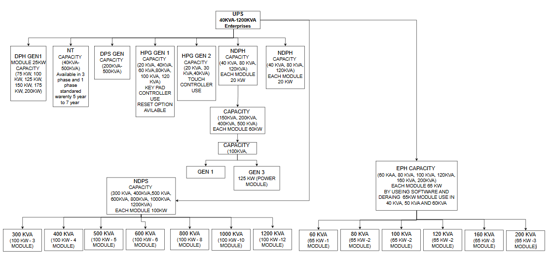
DPS GEN CAPACITY (200KVA- 500KVA)
HPG GEN 1 CAPACITY (20 KVA, 40KVA, 60 KVA,80KVA, 100 KVA, 120 KVA) KEYPAD CONTROLLER USE RESET OPTION AVILABLE
HPG GEN 2 CAPACITY (20 KVA, 30 KVA,40KVA) TOUCH CONTROLLER USE
NDPH CAPACITY (40 KVA, 80 KVA, 120KVA) EACH MODULE 20 KW
- CAPACITY (150KVA, 200KVA, 400KVA, 500 KVA) EACH MODULE 60KW
- CAPACITY (100KVA)- GEN 1, GEN 3 125 KW (POWER MODULE)
NDPH CAPACITY (40 KVA, 80 KVA, 120KVA) EACH MODULE 20 KW
NDPS CAPACITY (300 KVA, 400KVA,500 KVA, 600KVA, 800KVA, 1000KVA, 1200KVA) EACH MODULE 100KW
- 300 KVA (100 KW - 3 MODULE)
- 400 KVA (100 KW - 4 MODULE)
- 500 KVA (100 KW - 5 MODULE)
- 600 KVA (100 KW - 6 MODULE)
- 800 KVA (100 KW - 8 MODULE)
- 1000 KVA (100 KW -10 MODULE)
- 1200 KVA (100 KW -12 MODULE)
EPH CAPACITY (60 KAA, 80 KVA, 100 KVA, 120KVA, 160 KVA, 200KVA) EACH MODULE 65 KW BY USEING SOFTWARE AND DERATING
65KW MODULE USE IN 40 KVA, 50 KVA AND 60KVA
- 60 KVA (65 KW -1 MODULE)
- 80 KVA (65 KW -2 MODULE)
- 100 KVA (65 KW -2 MODULE)
- 120 KVA (65 KW -2 MODULE)
- 160 KVA (65 KW -3 MODULE)
200 KVA (65 KW -3 MODULE)
 CHANNEL
 1- 1 Phase Input, 1 Phase Output (Range 1KVA to 10 KVA)
2- 3 Phase input, 1 Phase output (Range 10 KVA to 20 KVA) GES502 Obsolete model
3- 3 Phase Input, 3 phase output (Range 10 KVA to 40 KVA)
EOL- End of life- 7 Year
Standard warranty- 1 to 2 Year
External Warranty- 5 Year
1> Single Phase UPS
Model INX- Range 1 kVA to 3 KVA Running Model
Model INXCE- Range 1 KVA to 3 KVA Running Model
N PRO- Range 1 KVA to 3 KVA
R- Range 1 KVA to 3 KVA Rack and Floor Mount
IN- Range 1 KVA to 3 KVA (EOL) Use in National insurance
EOS (End of Services)
Air Force
R Series- 1 KVA ( 1KVA to 3 KVA)
N series- 1 KVA to 3 KVA
Model
N PRO - Range 6 KVA to 10 KVA
RT- 5 KVA, 6 KVA, 10 KVA. 87 KVA customized
3 Phase Input 1 Phase Output
EOL- EH Model- 10 KVA, 15 KVA (Ageing in Reliance), 20 KVA (AMC, Charge)
Running RT model- 10 KVA, 15 KVA, 20 KVA
We can convert this 3 Phase input 1 phase output and 3 phase input and 3 phase output
3 phase Input and 3 phase output
GEN 1 (End of Life)
HPH- 20 KVA, 30 KVA, 40 KVA (Part Code- GES203HH)
GEN 2 (Running Model)
20 KVA, 30 KVA, 40 KVA (Part Code-UPS203HH)
DLC (Digital Line Conditioner (End of life) this is voltage stabilizer
Capacity- 20KW
CVCF (constant voltage constant frequency)- Use in petrol pump
Capacity- (20 KVA, 30 KVA, 40 KVA)
ATS (AUTOMATIC TRANSFER SWITCH)
Use in NMRC cabinet company name SCOMES
STS (Static Transfer Switch
Capacity 16A, 32A
3 phase input and 3 phase output
Wiring Diagram
MAINTENANCE BYPASS
Q3
┌──────────────────o/ o──────────────────┐
│ │
│ ▼
AC INPUT ──Q1──► RECTIFIER ── DC BUS ──► INVERTER ──► STATIC SW ──Q4──► LOAD
│
│
▼
BATTERY
Rectifier converts AC to DC.
Battery is connected to DC Bus.
Inverter converts DC back to AC.
Load receives conditioned UPS power.
Q3 (Maintenance Bypass) remains OFF.
Q1- Input MCB
Q2- Bypass MCB
Q3- Manual bypass MCB
Q4 Output MCB
How to read part code
GES203HH
Where 20 Show KVA, 3 show 3 phase, HH show series HPS
EPO
4 keys are there
ESC
DOWN
UP ENTER
ESC+ DOWN ARROW- Current Event Show.
Enter show Measurement option
There are 4 indicators use
1- Green- proper running no issue
2- Yellow- System work with fault identification
3- Bypass- System work in bypass mode
4- Fault- Fault come, System is not work.
We can reset fault by pressing off button up to 30 second. If problem is not resolved, then note the current event and log the TT number.
Voltage Range- 186 VAC to 265 VAC
CONDITION 1
R Phase Voltage 186 VAC, Y Phase voltage 186 VAC, B phase Voltage 186 VAC - System work properly in low side range.
Condition 2
R Phase Voltage 265VAC, Y Phase voltage 265VAC, B phase Voltage 265VAC - System work properly in higher side range.
Condition 3
R Phase Voltage 186VAC, Y Phase voltage 265VAC, B phase Voltage 265VAC - System does not work.
If the phase sequence is reversed, the system may also display a fault condition. In such cases, if feasible, interchange any two phases to correct the phase sequence. If phase interchange is not possible, advise the user to run the DG set and provide the turnaround time (TT) accordingly.
Switch Gear
Q3 Manual Bypass
input and manual bypass
General Fault in UPS
Phase Reverse Voltage- in this case say user to start DG and log TT
Under Voltage
Over Voltage
PFC shut Down
Short Circuit
Invertor Fail
Over Temperature- Reset Temperature >= 42*c
Overload
Fan Fail
Bypass SCR
Output fuses fail
Aux Power Fail- In this case UPS is not shut down, if we power off then system is completely shut down.
Battery polarity reversed
Manual Bypass
NTC open fail (Environmental issue)- If filter chock we have to clean filter.
Charge Fail
The System password is 0000
this is IGBT base UPS
20 KVA use 1 PFC
30 KVA use 2 PFC
40 KVA use 2 PFC
Rectifier-330VDC + PFC (Booster) + 380 VDC
Maintenance Page
we found serial number
60 KVA TO 120 KVA GEN 2 TOUCH PANEL
This system is not resettable
capacity- 60 KVA, 100 KVA, 80 KVA, 120 KVA)
Middle Fan with green connector
we can run system with fault, however if system is off then not able to start system further.
DPH series
GEN 1 Keypad controller
Module user 8 number
Each module 25 Kw (25 KW*8) =200KW
Range - 75 KW to 200 KW
controller is not hot swapable
THERE ARE 4 LED
1> NORMAL
2> BATTERY
3> BYPASS
4> FAULT
6 KEYS THERE
ESC
UP ARROW
DOWN ARROW
ENTER
ON SWITCH
OFF SITCH
If any invertor module fault, then release switch screw and remove this
if bypass mode active then press on button 30 Sec. Then system do self-Diagnosed.
GEN 2 NDPH
Capacity 300 KVA, 500 KVA, 600 KVA, 1000 KVA
Touch Panel Controller
100% hot swapable
Power Module
1540 KW use in 50 KW
1899 KW use in 60 KW
1000 KVA customized product
Power factor is Unity
For battery mode, bypass mode, soft start, minor alarm- Yellow LED Glow.
All heathy condition- Green LED glow
For Major Problem- Red LED glow
DPS Series
Model Number 204DS33RA09
This is Modular UPS
Controller is hot swapable
up to 10 module use
DPH Series
Model number UPS304DH33D2509
30 SHOW 300V
4 SHOW 4 WIRE
DH SHOW DPH SERIES
33D SHOW NUMBER
25 SHOW YEAR YY
09 SHOW MONTH MM
This is monolithic Auto reset alarm; we cannot reset alarm manually.
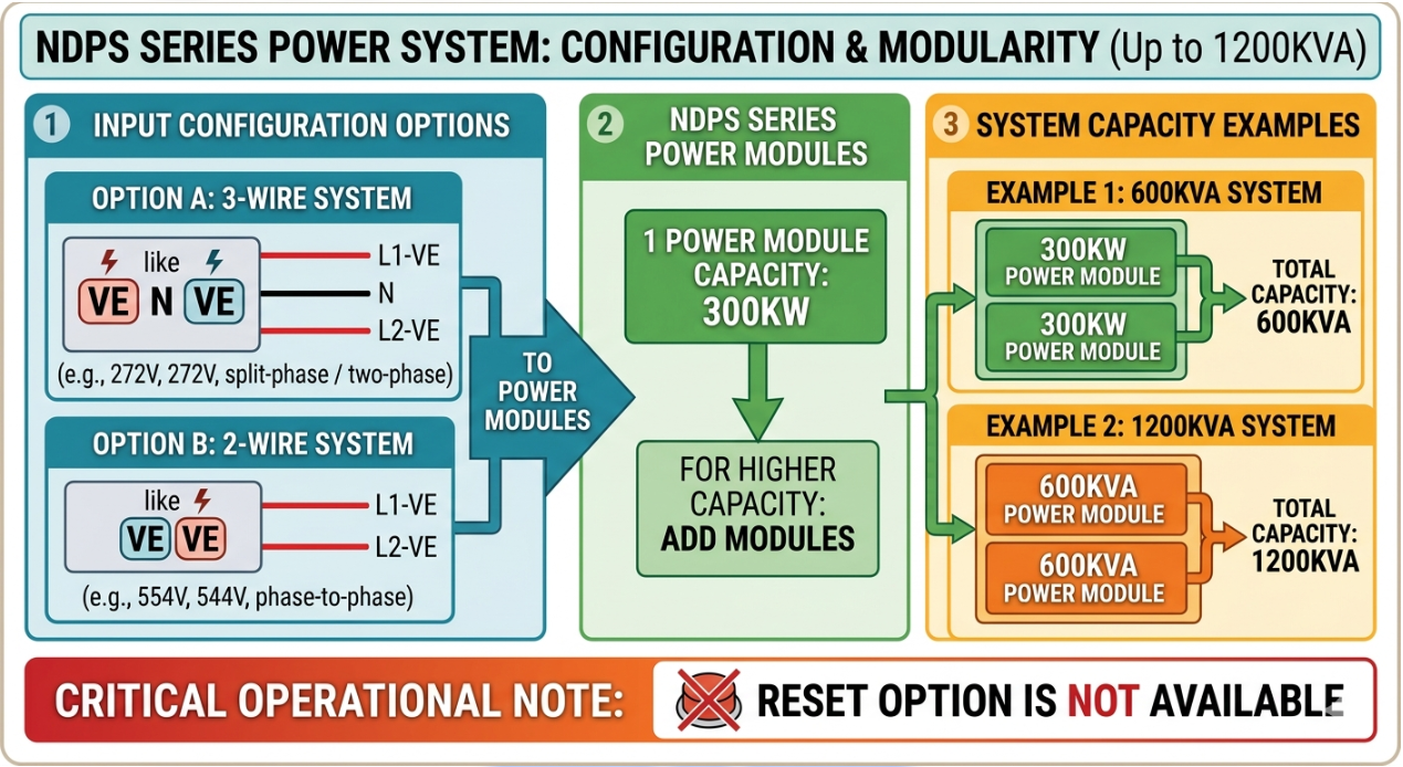
NDPS SERIES
This is available in 3 wire system like +VE, N, -VE (Eg +272V, -272V) and 2 wire system like +VE, -VE (Eg 554V)
Capacity up to 1200KVA
1 power module capacity is 300KW
In 600KVA use 2 power modules of 300KW
In 1200KA use 2 power modules of 600 KVA
Reset option is not available
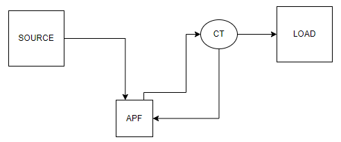
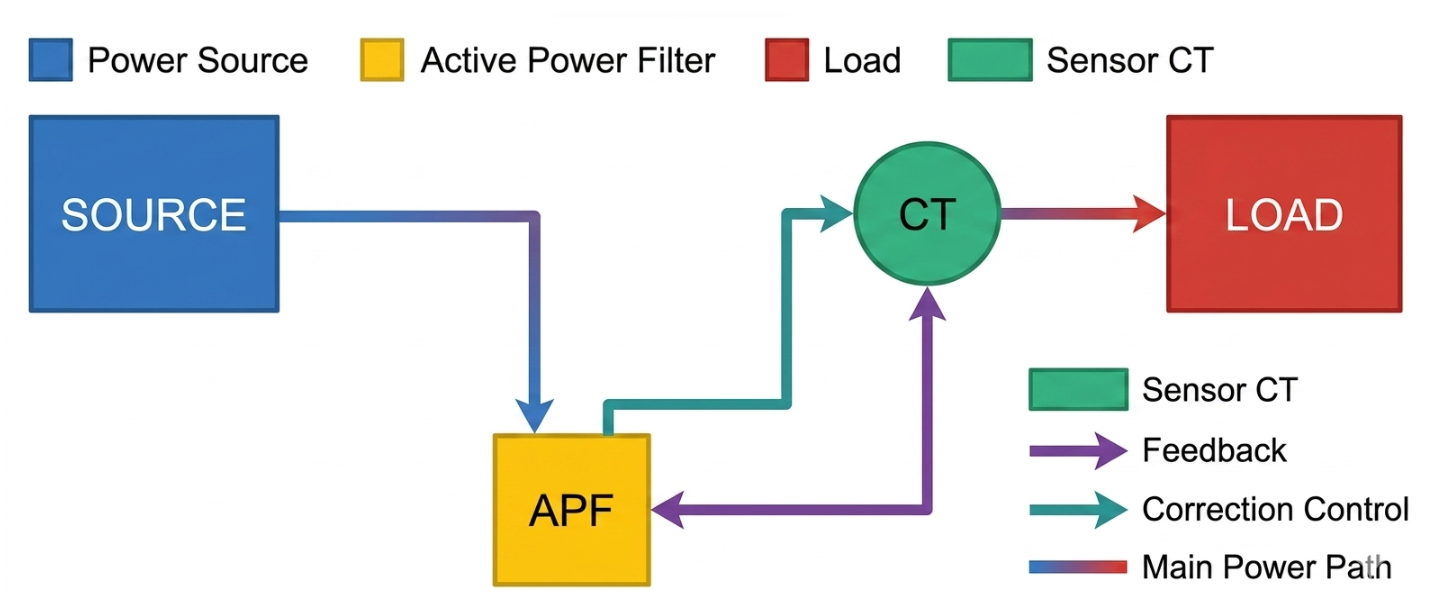
APF Use in Delta UPS
APF (Active Power Filter) is used with Delta UPS systems to improve overall power quality by eliminating harmonics and compensating reactive power in the electrical network.
Static Var Generator (SVG)
is a fast-acting, dynamic power quality device. It connects in parallel with your system and continuously monitors the load. By injecting precise leading or lagging current, it cancels out reactive power (VAR) and instantly improves your power factor to near unity (≥ 0.99).
LI-ION BATTERY use in UPS
no. of quantity 8 no. to 10 no.
Battery capacity is 60 AH.
Online UPS double conversion system.
The UPS operates on Online Double Conversion Technology, which provides zero transfer time during utility power failures.
In normal operation, the AC source is supplied to the rectifier, which converts AC power into DC power. The rectifier output is connected to both the battery bank and the inverter. The inverter continuously converts the DC power back into regulated AC power and supplies it to the load.
In the event of an AC source failure, the battery bank immediately supplies DC power to the inverter. Since the inverter is already supplying the load, there is no switching delay or interruption in output power. This is known as a Double Conversion UPS system and ensures zero transfer time.
The load is connected through a Static Transfer Switch (STS) or Automatic Transfer Switch (ATS). In case of an inverter fault, control circuit failure, UPS overload, or maintenance condition, the STS automatically transfers the load to the bypass source. Where an AVR (Automatic Voltage Regulator) is provided in the bypass path, the load continues to receive regulated power from the bypass source.
This configuration ensures continuous and reliable power supply to critical loads under all operating conditions.